Smart car obstacle avoidance system with Arduino as the core control
2021-04-19
Artificial intelligence technology is a cutting-edge technology that closely links with multiple basic disciplines and promotes mutual development. It is a high-tech industry integrating computer, physics, physiology, control technology and sensor technology. The application fields of artificial intelligence technology are also becoming more and more extensive. In addition to the traditional industrial field, the application of artificial intelligence technology also involves military, entertainment, service, medical and Other fields.
This article refers to the address: http://
With the continuous development of robot technology, people's requirements for robots are getting higher and higher, and the intelligence of robots has become a hot spot today. As a kind of four-wheel drive intelligent robot, the smart car is flexible and easy to operate. It can integrate various precision sensor data processing modules on the car. Its obstacle avoidance function ensures the self-adjustment of the traveling direction of the smart car during the travel, avoiding Collision and rubbing are important parts of a smart car. At present, smart cars mostly use single sensors to achieve single-sided obstacle avoidance, but there are inherent defects in single-sided obstacle avoidance, such as: slow detection of obstacles and low success rate of obstacle avoidance. Therefore, a smart car system capable of avoiding obstacles in all directions is designed. The combination of infrared single-point obstacle avoidance and ultrasonic double-track obstacle avoidance can realize multi-faceted automatic detection and realize all-round obstacle avoidance, effectively improving The success rate and efficiency of obstacle avoidance.
1 system design
The designed obstacle avoidance system adopts a combination of infrared single-point obstacle avoidance and ultrasonic double-track obstacle avoidance to achieve an all-round effective obstacle avoidance for obstacles. To this end, an infrared obstacle avoidance sensor is arranged in the center of the front end of the trolley for detecting obstacles in front of the trolley, and then two left and right ultrasonic obstacle avoidance sensors are arranged on both sides of the front end of the trolley, and they respectively detect obstacles on the left and right sides of the trolley, which are effective. The scope of detection has been expanded, thus achieving the full obstacle avoidance of the trolley.
The system utilizes multi-module coordination to make it highly adaptive. Based on the requirements, the hardware selects the appropriate module. The overall module includes: power module, infrared sensor module, Ultrasonic Sensor module, motor driver module, Arduino module. The overall block diagram of the system is shown in Figure 1.
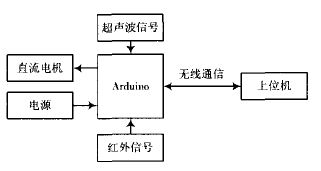
Figure 1 system hardware structure diagram
1.1 Arduino module
Arduino duemilanove is used as the core control module in the design. Arduino is an easy-to-use and easy-to-use open source electronic prototyping platform that can sense the environment through various sensors and feedback and influence through lights, motors and other devices. surroundings.
The Arduino duemilanove consists of the following sections: a 9 V DC input, a USB interface, 14 digital IO ports, 6 analog IO ports, a 5 V DC output and a 3.3 V DC output. At its core is an Atmega 328 microcontroller.
1.2 Motor Module
The trolley adopts dual DC motor drive mode to control the turning and steering of the trolley by controlling the left and right DC motors. The motor module is shown in Figure 2. The DC motor uses the DC motor drive chip L298N.
The L298N contains a 4-channel logic driver circuit. It is a dedicated driver for two-phase and four-phase motors. It is a high-voltage, high-current, dual-bridge driver with two H-bridges. It receives standard TTL logic level signals and can drive 46. The motors below V and 2 A can meet the driving requirements of the left and right DC motors of the trolley. And L289N has an over-temperature protection function and a high noise suppression ratio, so it is very suitable for use in smart cars.
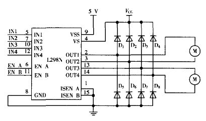
Figure 2 Motor Module
Since the chip L298N does not control the motor speed, the Arduino program controls the PWM signal of the drive motor to change the output power of the motor, thereby controlling the speed of the left and right motors.
1.3 Ultrasonic sensor module
The ultrasonic module is composed of a transmitting circuit and a receiving circuit, as shown in FIG. The transmitting circuit is composed of Em78p153 single chip microcomputer, MAX232 and ultrasonic transmitting head T40, and the receiving circuit is composed of TL074 operational amplifier and ultrasonic receiver R40.
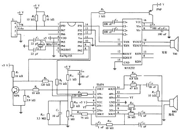
Figure 3 ultrasonic sensor
At the time of detection, the ultrasonic transmitter emits an ultrasonic signal with a length of about 6 mm and a frequency of 40 kHz. This signal is reflected by the object and received by the ultrasonic receiver, which is essentially a piezoelectric effect transducer. After receiving the signal, it generates a weak voltage signal of mV level, and the voltage signal is converted into a digital signal in the core control module. It is assumed that the time elapsed from the time when the ultrasonic pulse is emitted from the sensor to the reception is t, and the propagation speed of the ultrasonic wave in the air is c, and the distance D from the sensor to the target object can be obtained by D=ct/2.
1.4 infrared sensor module
The infrared ranging module adopts the Sharp GP2YOA21 infrared ranging sensor. The Sharp GP2YOA21 infrared ranging sensor is a macro sensor based on the position sensitive sensor PSD (Position Sensitive Device), which captures the optical signal and has a circuit design based on the Lukovusky equation. The effective measuring distance is 80 cm.
The advantage of infrared ranging is that there is no blind zone, high measurement accuracy and fast response speed, but its shortcomings are greatly affected by the environment and the detection distance is close. Therefore, this paper designs a smart car obstacle avoidance system based on multi-sensor information fusion, which uses infrared sensors and ultrasonic sensors to complement each other, so that the robot has an accurate sensing range.
2 algorithm analysis
Aiming at the shortcomings of the single-sensor obstacle avoidance system, this paper proposes a multi-sensor coordination cooperation scheme, which expands the detection range and sensitivity by the cooperation of the ultrasonic sensor and the infrared sensor, thereby avoiding the danger of accidental collision and close to obstacles. The obstacle avoidance rate has been improved, and obstacle avoidance has been realized.
2.1 Process design
During the travel of the all-round obstacle avoidance car, each sensor continuously detects whether there are obstacles around the car. When a sensor detects an obstacle, the vehicle automatically detects obstacles by judging the number of sensors that detect the obstacle: when the single sensor detects the obstacle, the trolley moves away from detecting the obstacle direction; two sensors detect In the case of obstacles, the car turns toward the direction in which no obstacle is detected; when all the sensors detect the obstacle, the car quickly turns left to avoid the obstacle. When the car avoids the obstacle, the car continues to travel. The flow chart is shown in Figure 4.
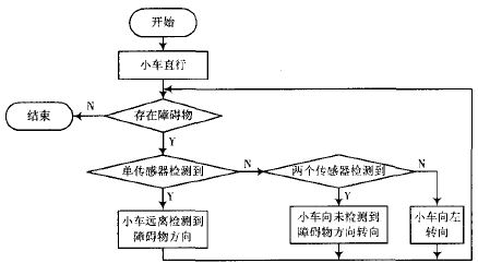
Figure 4 program flow chart
2.2 Obstacle Avoidance Code
According to the above obstacle avoidance principle, the corresponding program is written to realize the comprehensive obstacle avoidance of the trolley. The program is mainly divided into three parts: motor, ultrasonic and infrared ranging. The motor part is controlled by analogWrite() and digitalWrite() to control the speed and the car forward, backward or steering respectively; the ultrasonic measuring part is controlled by the Trig.Pin ultrasonic input, and the EchoPin controls the ultrasonic output. The control module performs the pulse wave time received. Processing, converted into a distance parameter, thereby obtaining the distance Middle_distance; the infrared ranging portion is obtained by the control module through the infrared sensor to obtain an analog amount anal.gRead(), and the output voltage can be used to derive the voltage value volts, and the output voltage and the detection distance The relationship is distance: 65*pow(volts, -1.10), so that the distance between the car and the obstacle can be obtained.
Industrial Laser Distance Sensor, we also call it secondary development laser distance module, which support TTL level and CMOS. The laser range sensor can be widely used in professional surveying, mapping, construction, robots, hunting arrows, industrial monitoring and automated measurement applications in electricity, transportation, etc. Our laser distance module supports data communication with RS232, USB with a simple adapter. The results of laser distance sensor can be evaluated with Arduino. We are always looking ahead, hoping we can make every measurement simple in life!

Parameters of M703A:
|
Accuracy |
±1 mm (0.04 inch) |
|
Measuring Unit |
mm |
|
Measuring Range (without Reflection) |
0.03-60m(150m can customize) |
|
Measuring Time |
0.125~3 seconds |
|
Laser Class |
Class II |
|
Laser Type |
620-690nm, <1mW |
|
Size |
45*25*12mm (±1 mm) |
|
Weight |
About 10g |
|
Voltage |
DC2.0~3.3V |
|
Electrical Level |
TTL/CMOS |
|
Frequency |
8Hz(20Hz can customize) |
|
Operating Temperature |
0-40 ℃ (32-104 ℉ ) |
|
Storage Temperature |
-25~60 ℃ (-13~140 ℉) |
Laser Distance RS232, Arduino Distance Module, Laser Module RS232
SWT Smart Technology Co., Ltd. http://www.rangingsensor.com